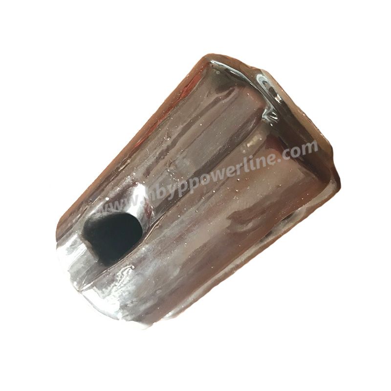
Composite Insulator
Inquire NowNone

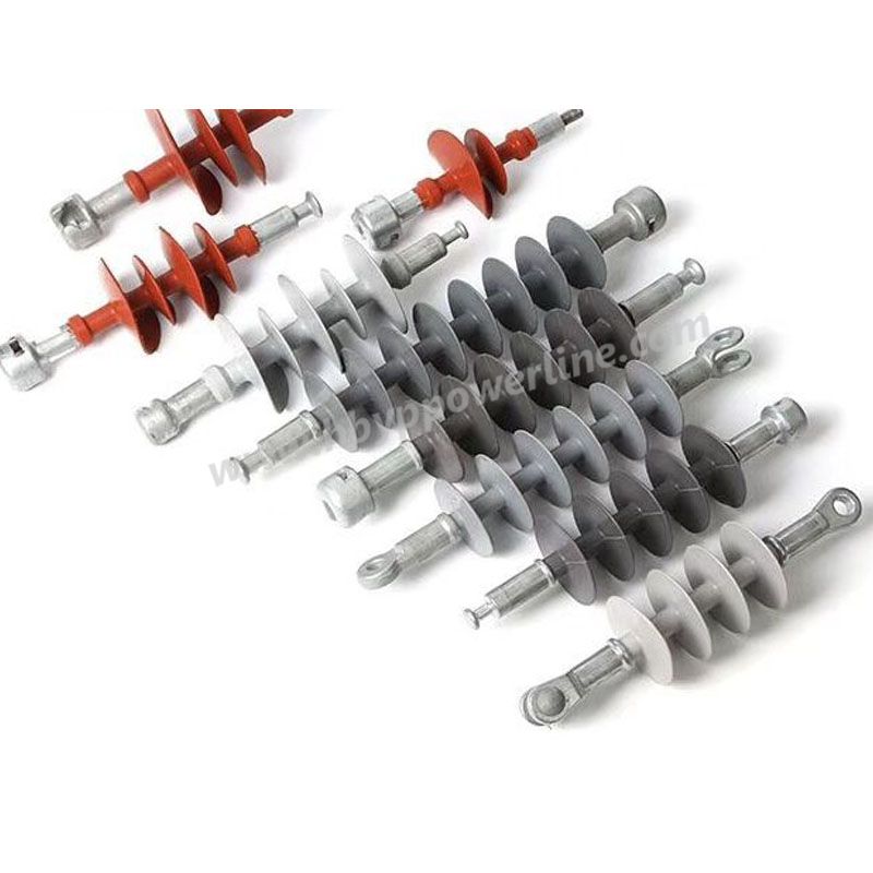
Yipeng manufactures and supplies silicone rubber composite insulators for power transmission, distribution and substation projects. Product selection should be based on the insulator function, electrical insulation level, mechanical duty, creepage requirement, installation dimensions and connection interfaces rather than voltage class alone.
A composite insulator is a multi-material insulation component in which different parts perform different functions. A typical design uses a load-bearing FRP core, an external polymeric housing and metal end fittings.
For procurement purposes, the important point is not simply that the insulator uses silicone rubber. The complete assembly must provide the required electrical insulation, mechanical strength and connection geometry for its specific position on the line.
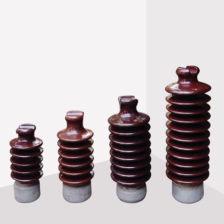
Common composite insulator configurations include suspension or tension long-rod insulators, line-post insulators, pin-type insulators and products designed for substation equipment. These configurations are not interchangeable because their mechanical loading and mounting interfaces are different.
Start with the position of the insulator in the electrical system.
Suspension and tension arrangements normally place significant tensile load through the insulator and its end fittings. Their specification therefore commonly includes a specified mechanical load, coupling arrangement, structural length, creepage distance and electrical withstand ratings.
Line-post applications carry the conductor through a comparatively rigid support arrangement. Cantilever or bending performance, base configuration and conductor-side fitting become important selection parameters.
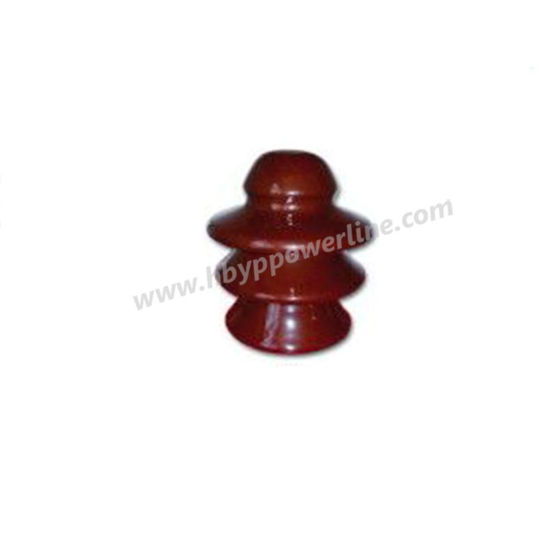
Pin-type arrangements require the insulator geometry and mounting interface to match the supporting pin, cross arm and conductor arrangement.
For substation applications, identify the exact equipment and support function. A line insulator and a substation support insulator may use similar composite materials but have different mechanical and dimensional requirements.
Mechanical rating should be selected according to the insulator function.
For suspension and tension composite insulators, project specifications commonly define a tensile mechanical rating such as SML. For line-post and other rigid support arrangements, cantilever or bending requirements may be more relevant.
Do not select a composite insulator by voltage alone. Two products designed for the same nominal system voltage can have different mechanical ratings and therefore cannot automatically be substituted for one another.
Include the required mechanical load or the governing utility drawing in the RFQ.
Nominal voltage identifies only part of the electrical requirement.
Depending on the project and applicable standard, buyers may also need to specify:
highest system voltage;
lightning impulse withstand requirement;
dry or wet power-frequency withstand voltage;
dry arcing distance;
minimum creepage distance; and
other insulation-coordination requirements defined by the utility specification.
Where these values are already stated in a tender or technical specification, provide the specified values rather than requesting a product only by voltage class.
Creepage distance is the surface path between conductive parts of the insulator and is an important parameter where contamination can affect external insulation performance.
Selection should consider the pollution conditions defined for the project. Coastal salt contamination, industrial pollution, dust and other service environments may require different creepage or shed-profile requirements from a normal inland installation.
If the project already specifies minimum creepage distance or a pollution class, include that requirement in the enquiry. If it does not, provide the operating environment and applicable utility or project specification for review.
The number of sheds alone should not be used as the primary selection criterion because different shed geometries can produce different creepage distances.
An insulator can meet the electrical and mechanical ratings but still be unsuitable if its interfaces do not match the existing line hardware.
Depending on the insulator function, relevant connection details may include:
ball-and-socket couplings;
clevis or tongue arrangements;
blades;
mounting bases;
conductor clamps;
pin or spindle interfaces; and
project-specific fitting dimensions.
For replacement projects, provide the existing model, coupling designation or dimensional drawing.
Where the composite insulator forms part of a larger line assembly, the insulator and associated fittings should be checked together before the order is finalized.
| Project Condition | Main Parameters to Check | Why It Matters |
|---|---|---|
| Suspension or tension line position | SML, structural length, creepage, end fittings | The insulator must carry tensile load while matching the line hardware |
| Line-post application | Cantilever/bending requirement, base, conductor-side fitting, creepage | Mechanical loading and mounting differ from long-rod tension designs |
| Pin-type application | Pin interface, dimensions, mechanical requirement and electrical rating | The insulator must match both the supporting pin and conductor arrangement |
| Polluted or coastal environment | Creepage, shed profile and material requirement | Surface contamination changes external insulation requirements |
| Replacement project | Existing model, length, interfaces and electrical/mechanical ratings | Similar voltage does not guarantee interchangeability |
| Utility/tender project | Exact standard, drawing, testing and documentation requirements | Technical acceptance is controlled by the project specification |
| Higher-voltage application | Insulation level, arcing distance and required grading hardware | Electric-field and insulation coordination become important design considerations |

Composite insulators operate as part of a complete transmission or distribution assembly.
For suspension and tension arrangements, the selected end fittings must match the corresponding tower-side and conductor-side line hardware. Review our overhead line fittings when an insulator will be purchased together with connection hardware.
For pin-supported structures, the interface should be checked against the insulator pin or spindle and the required electrical cross arm.
When several components belong to the same pole or tower structure, include an assembly drawing or bill of materials in the enquiry. This allows mounting dimensions and interfaces to be reviewed together instead of selecting each component independently.
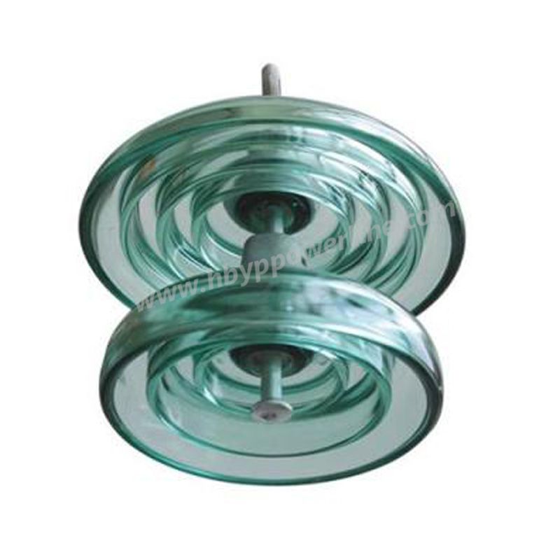
For projects comparing other insulation technologies, see Yipeng's porcelain insulators and glass insulators.
Yipeng accepts enquiries involving OEM and customer-specific composite-insulator requirements.
Because the required changes depend on the selected product type, identify the requested parameters clearly in the technical specification. These may include requested dimensions, electrical or mechanical ratings, creepage requirements, shed/profile requirements, end-fitting interfaces, grading hardware or marking requirements.
Feasibility should be confirmed against the selected design before the customized requirement is included in the purchase specification.
A drawing or complete technical data sheet provides a better basis for review than a description such as “33 kV polymer insulator” alone.
Explosion-proof for maximum safety
Non-brittle material to reduce the risk of damage during handling
Leakage current control through hydrophobicity
Excellent insulation for reduced creepage distances
Flashover resistance
Excellent shock resistance for safety and reliability
Light weight for cost savings
Maintenance-free and excellent contamination performance
UV stability
For high voltage applications and substations
Composite insulators can be divided into: line composite insulators and power station and power composite insulators. It can also be divided into rod suspension composite insulator, pin composite insulator, cross arm composite insulator, pillar composite insulator, windproof part composite insulator, composite column insulator, etc.
The structure of composite insulators varies according to the usage characteristics. In addition to meeting the tensile strength, satisfying the requirements, and being reliably connected to the mandrel, the metal tip needs to be designed to meet the special requirements for application under high voltage. Composite insulators are generally made in the form of rods with very small capacitance. As a result, the voltage distribution on the insulator surface is very uneven. The resulting corona is therefore harmful in normal operation and therefore requires the use of voltage equalization measures. In addition, the synthetic insulating material cannot withstand an arc of several tens of kA. In case of a short-circuit fault, it will burn the umbrellas near the wires and towers, so arc pulling is required. At home and abroad, the
The equalizing ring of the composite insulator is an integral part of the composite insulator. Its role is to control the electric field strength inside the insulator, avoid internal partial discharge, reduce the local electric field strength on the outer surface, especially on the surface of the metal connection part, and reduce radio interference. It draws out the industrial frequency arc, avoids burning the insulator surface, minimizes the local electric field strength near the end face, and improves its anti-fouling performance.
In overhead-line procurement, the terms are commonly used for insulators that combine a load-bearing composite core with a polymeric external housing and metal end fittings. The purchase specification should still identify the exact product type, material requirements and performance ratings rather than relying on the name alone.
No. Voltage class does not define the mechanical load, creepage distance, structural length or end-fitting configuration. Specify the insulator function and these additional parameters before selecting a model.
SML is particularly relevant to composite long-rod insulators that carry tensile loads in suspension or tension arrangements. Line-post configurations are subjected to different loading and commonly require cantilever or bending performance to be considered. Use the mechanical requirement stated in the line or utility design.
Provide the original model or technical drawing where available. Confirm the structural length, creepage distance, mechanical rating, electrical ratings, end fittings and coupling dimensions. Photographs can help identify the arrangement but should not replace controlled dimensions.
Not necessarily. Grading or corona-control hardware depends on the electrical design, voltage level, insulator geometry and applicable project specification. Follow the approved product design or utility requirement rather than adding or removing grading hardware based only on voltage class.
Yipeng also supplies overhead line fittings and other pole-line hardware. Include the assembly drawing or bill of materials when the insulator and associated fittings must operate together so the relevant connection interfaces can be reviewed during quotation.
Please contact us, we are ready to solve your problem!
+86 319 878 9350
+86 156 1304 7999
+86 319 878 9350
NanYan, DongHuan Road, Shahe, Hebei China
Copyright © Hebei Yipeng Line Equipment Co., Ltd. All Rights Reserved. | Sitemap Powered By